
Active receive antenna · Radio club workshop
Voltage Probe Antenna — the MiniWhip club build
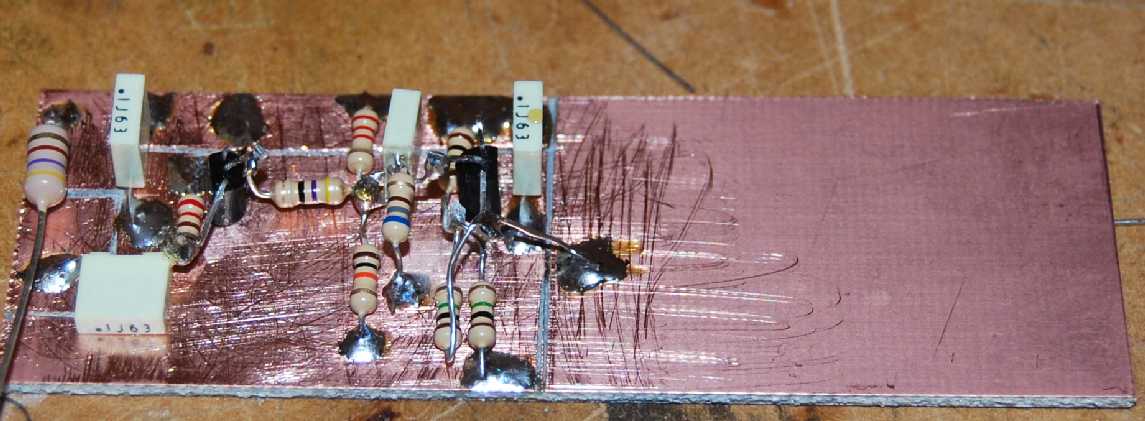
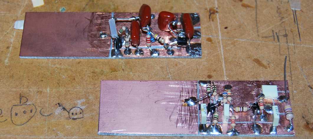
I took this project round several radio clubs. We started with a talk about the antenna, then got out the soldering irons and built it. The photographs here come from the constructor’s guide I used at those sessions, where I could also show a builder which copper island or transistor lead I meant.
The circuit is based on the PA0DRT Mini Whip. I claim no originality for either the circuit or the two-board arrangement. This is my account of how we built it on pieces of copper-clad board.
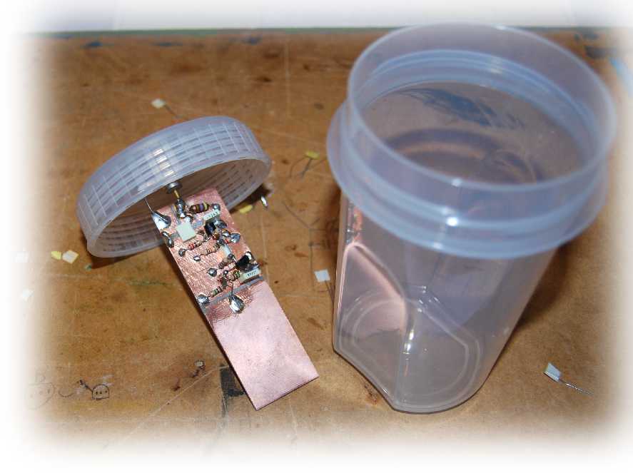
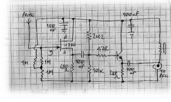
The circuit and the two boards
A small copper plate senses the RF electric field. A high-impedance JFET input stage follows the voltage on the plate, and a bipolar output stage drives the coax. In the club build the coax also carries DC supply to the mast-top board. The separate DC feed board, or bias tee, injects that supply into the coax and blocks it from reaching the receiver input.
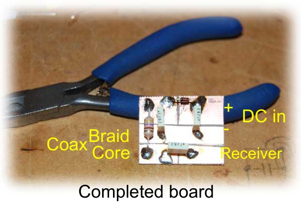
Build the DC feed board
- Workshop parts
- 25 × 30 mm copper-clad board, one 470 µH choke, three 100 nF capacitors and one 1N4148 diode.
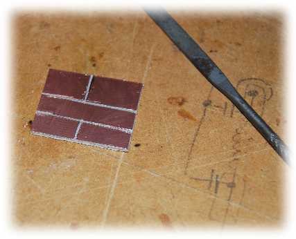
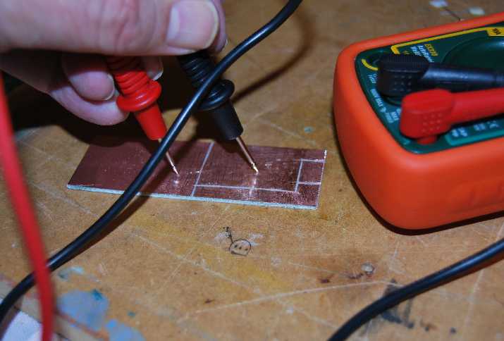
- Mark out the copper islands and file through the copper with a needle file. Use a meter to check continuity within each island and isolation across the cuts.
- Fit the series capacitor between the mast-side and receiver-side signal connections. Fit the two decoupling capacitors from their respective DC islands to the common ground track.
- Fit the choke between the DC feed and the mast-side coax centre connection. Fit the series diode in the supply path, with the unbanded anode on the incoming positive supply side and the banded cathode on the protected side that feeds the choke. Trace those connections on the copper before soldering.
Build the mast-top board
- Workshop parts
- 90 × 30 mm copper-clad board, a J310 JFET, a 2N3904 NPN transistor as supplied in the kits, a 470 µH choke, four 100 nF capacitors and resistors of 47 Ω, 220 Ω, 680 Ω, 2.2 kΩ, 10 kΩ and three of 1 MΩ.
Prepare the copper layout
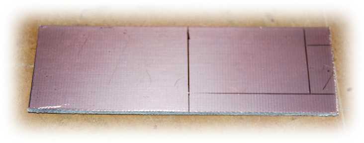
Mark out the large sensing plate, the ground plane, the coax-centre island and the DC supply rail. File the isolation cuts and check them with a meter. Clean the copper where you plan to solder.
Fit the feed components and the output stage
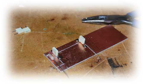
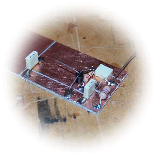
Solder the choke to the DC rail and leave its coax end free while assembling the rest of the circuit. Fit the decoupling capacitors, then the 220 Ω emitter resistor and the capacitor that couples the output to the coax-centre island. The 47 Ω resistor goes in series with the NPN base. Check the pinout of your actual transistor and resolve the divider discrepancy above before wiring the two bias resistors.
Fit the JFET and finish the probe
The J310 source feeds the coupling capacitor into the NPN stage and has a 680 Ω return to ground. Its drain goes to the DC rail. The three 1 MΩ resistors form part of the gate network by the copper sensing plate. Check the pinout against the data sheet for the actual device in your hand. The pictures in the guide show the parts supplied in the workshop kits.
Keep the point-to-point leads short. Once you have inspected the joints and checked for shorts, connect the free end of the choke to the coax-centre island. The coax braid goes to the ground plane.
Checks before connecting a receiver
- With the power off, inspect the cuts and solder joints. Check for an unintended short between the supply and ground and between the coax centre and braid.
- Power the bias tee on its own with the receiver and mast-top board disconnected. Measure from each coax centre connection to ground. There should be DC on the mast side and no steady DC on the receiver side.
- Switch off before connecting the mast-top board. After powering both boards, check again that no DC reaches the receiver-side connector before plugging in the receiver.
This is a receive-only antenna. Do not connect it to a socket that can transmit.
The workshop handout
Download the VPA builder’s guide (PDF, 10 pages). Before building from the guide, check the note on the NPN bias divider.